For my stupid pet trick, I wanted to create something that would be kind of dumb, but like a game to play with. After struggling foreverrrrrrrr to come up with an idea, I decided to start from the opposite route. I began by messing around with a few different codes and circuits. One of the circuits and codes I created was a random number generator. That made me think of a dice and the applications that could have in real life.
I began thinking of board games and how that could be a used. I then was thinking about just how random the blinking lights were, and guessing which one would come next was near impossible. Then, it struck me that a lottery would be the perfect setup to use this!
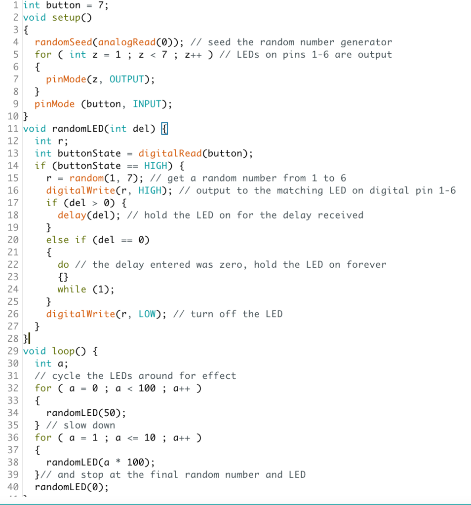
I decided to make a lottery box. The way it worked was that a press of a button would trigger the lights to randomize and see if it matched up with the number drawn. I then had to go back into the code and add in the ‘if’ statement for the button. However, I was not able to make the button so that one click would trigger the motion, rather, the button had to stay consistently down in order to work. This was due to the amount of delays in the code.
I ended up laser printing the sides of the box out of cardboard and hot glueing them together. As for the lights, I soldered wires of the right length on to them, as well as the button. I then simply painted the boxand printed out a few instructions toadd to the game so that it made more sense, and voila.
For this week’s project, I was brainstorming the possible human motions that I could create using a motor. (Also, I didn’t use a DC motor for my final project because I thought that using a servo counted as using a motor oops).
While brainstorming, everytime me and a friend would come up with an idea, we would high-five each other. The ideas would end up not working, mainly due to technical reasons and because I would then look back and be like “nah I don’t like it anymore”. After a while, it hit me that a high-five would be a great human motion, used in everyday life, that could easily be replicated.
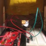
I simply cut out a hand shape from styrofoam, glued it onto a cardboard piece, and attached it to a servo that was then attached to wood for stability.
As for the coding, all I did was adjust the angle of the servo’s movement so that it would go back and forth consistently.
Looking back, it would’ve been really cool to add some sort of button, like a photocell, that would detect when someone was moving in for a high-five, and then trigger the movement.
This project is a representation of the state of a stressed out college student, say during midterms or finals. If you touch it, this is what happens:
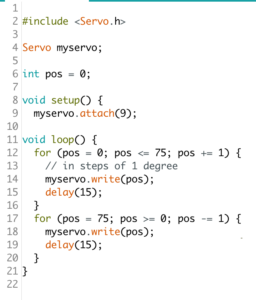
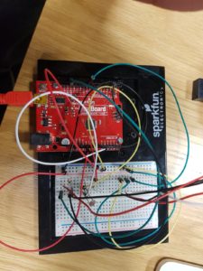
Here is a picture of the internals:
It is basically an Arduino with an mp3 shield controlling the speaker, reading from an SD card, and a motor shield stacked on top of it to control the motor. The motor shield was needed in order to change the direction of rotation of the motor in order to produce the ‘shaking’ effect. And out of the motor shield is a wire sticking out and taped to the box in order to measure capacitance, which is how I’m detecting touch.
Here’s the code:
#include <Wire.h>
#include <Adafruit_MotorShield.h>
#include <SPI.h>
#include <Adafruit_VS1053.h>
#include <SD.h>
#include "pins_arduino.h"

// These are the pins used for the music maker shield
#define SHIELD_RESET  -1      // VS1053 reset pin (unused!)
#define SHIELD_CS     7      // VS1053 chip select pin (output)
#define SHIELD_DCS    6      // VS1053 Data/command select pin (output)
#define CARDCS 4     // Card chip select pin
#define DREQ 3       // VS1053 Data request, ideally an Interrupt pin

// initialize mp3 shield
Adafruit_VS1053_FilePlayer musicPlayer = Adafruit_VS1053_FilePlayer(SHIELD_RESET, SHIELD_CS, SHIELD_DCS, DREQ, CARDCS);

// initialize motor shield
Adafruit_MotorShield AFMS = Adafruit_MotorShield(0x60);
Adafruit_DCMotor *wheels = AFMS.getMotor(2);

int delayval = 100;
const int touchPin = A1;

void setup() {
  // put your setup code here, to run once:
  Serial.begin(9600);
  AFMS.begin();
  //  wheels->setSpeed(255);
  //  wheels->run(FORWARD);
  //  wheels->run(RELEASE);
  if (! musicPlayer.begin()) { // initialise the music player
    Serial.println(F("Couldn't find VS1053, do you have the right pins defined?"));
    while (1);
  }
  Serial.println(F("VS1053 found"));
  if (!SD.begin(CARDCS)) {
    Serial.println(F("SD failed, or not present"));
    while (1);  // don't do anything more
  }
  musicPlayer.setVolume(1, 1);
  musicPlayer.useInterrupt(VS1053_FILEPLAYER_PIN_INT);
  //  Serial.println("playing music");
  //  musicPlayer.playFullFile("track001.mp3");
  //  printDirectory(SD.open("/"), 0);
}


void loop() {
  int capacitance = readCapacitivePin(touchPin);
  Serial.println(capacitance);
  if (capacitance > 5) {
    if (!musicPlayer.playingMusic) {
      musicPlayer.startPlayingFile("scream.mp3");
    }
    wheels->run(FORWARD);
    wheels->setSpeed(255);
    delay(delayval);
    wheels->run(BACKWARD);
    wheels->setSpeed(255);
    delay(delayval);
    wheels->run(FORWARD);
    wheels->setSpeed(255);
    delay(delayval);
    wheels->run(BACKWARD);
    wheels->setSpeed(255);
    delay(delayval);
    wheels->run(FORWARD);
    wheels->setSpeed(255);
    delay(delayval);
    wheels->run(BACKWARD);
    wheels->setSpeed(255);
    delay(delayval);
  } else {
    wheels->run(RELEASE);
  }
  delay(1);
}

uint8_t readCapacitivePin(int pinToMeasure) {
  // Variables used to translate from Arduino to AVR pin naming
  volatile uint8_t* port;
  volatile uint8_t* ddr;
  volatile uint8_t* pin;
  // Here we translate the input pin number from
  //  Arduino pin number to the AVR PORT, PIN, DDR,
  //  and which bit of those registers we care about.
  byte bitmask;
  port = portOutputRegister(digitalPinToPort(pinToMeasure));
  ddr = portModeRegister(digitalPinToPort(pinToMeasure));
  bitmask = digitalPinToBitMask(pinToMeasure);
  pin = portInputRegister(digitalPinToPort(pinToMeasure));
  // Discharge the pin first by setting it low and output
  *port &= ~(bitmask);
  *ddr  |= bitmask;
  delay(1);
  uint8_t SREG_old = SREG; //back up the AVR Status Register
  // Prevent the timer IRQ from disturbing our measurement
  noInterrupts();
  // Make the pin an input with the internal pull-up on
  *ddr &= ~(bitmask);
  *port |= bitmask;

  // Now see how long the pin to get pulled up. This manual unrolling of the loop
  // decreases the number of hardware cycles between each read of the pin,
  // thus increasing sensitivity.
  uint8_t cycles = 17;
  if (*pin & bitmask) {
    cycles =  0;
  }
  else if (*pin & bitmask) {
    cycles =  1;
  }
  else if (*pin & bitmask) {
    cycles =  2;
  }
  else if (*pin & bitmask) {
    cycles =  3;
  }
  else if (*pin & bitmask) {
    cycles =  4;
  }
  else if (*pin & bitmask) {
    cycles =  5;
  }
  else if (*pin & bitmask) {
    cycles =  6;
  }
  else if (*pin & bitmask) {
    cycles =  7;
  }
  else if (*pin & bitmask) {
    cycles =  8;
  }
  else if (*pin & bitmask) {
    cycles =  9;
  }
  else if (*pin & bitmask) {
    cycles = 10;
  }
  else if (*pin & bitmask) {
    cycles = 11;
  }
  else if (*pin & bitmask) {
    cycles = 12;
  }
  else if (*pin & bitmask) {
    cycles = 13;
  }
  else if (*pin & bitmask) {
    cycles = 14;
  }
  else if (*pin & bitmask) {
    cycles = 15;
  }
  else if (*pin & bitmask) {
    cycles = 16;
  }

  // End of timing-critical section; turn interrupts back on if they were on before, or leave them off if they were off before
  SREG = SREG_old;

  // Discharge the pin again by setting it low and output
  //  It's important to leave the pins low if you want to
  //  be able to touch more than 1 sensor at a time - if
  //  the sensor is left pulled high, when you touch
  //  two sensors, your body will transfer the charge between
  //  sensors.
  *port &= ~(bitmask);
  *ddr  |= bitmask;

  return cycles;
}
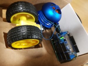
My project this week is literally a finger pointer. It is flat and moves 360 degrees and points to a location randomly. Ideally there would be people around in a circle and when I click the reset button it will turn and point randomly to one person.
I made it more appealing by accelerating the rotation from rest to a high speed and made it random by varying the acceleration randomly by changing the delay value.
Here’s a video of it working:
I’ve also attached the code I used:
const int motorPin = 9;


void setup()
{
    pinMode(motorPin, OUTPUT);
  Serial.begin(9600);
  motorAcceleration();
}


void loop()
{

}


void motorAcceleration()
{
  int speed;
  int delayTime = random(5,25);

  for(speed = 0; speed <= 255; speed++)
  {
    analogWrite(motorPin,speed);
    delay(delayTime);
  }


  for(speed = 255; speed >= 0; speed--)
  {
    analogWrite(motorPin,speed);    // set the new speed
    delay(delayTime);               // delay between speed steps
  }
  delay(1000);
}
As this week’s prompt is to use a motor to make a human action/emotion, I decided that I wanted to develop on my plant pot project that I had for the midterm.
Because my project then was already essentially anthromorphosising the plant pot into having human characteristics – the raising of the brows and/or the frowning of them – I wanted to develop something that would make it even more human.
Human/Robotic Legs – DISASTER STRIKES
I initially stuck two servos together to build a leg (so I had 4 servos) and angled and programmed them so that they could essentially have some sort of movement that allows them to move forward (the code for it I found online and just made some minor adjustments). The legs worked at first and I thought that I had finished with the assignment but then I realised that two of the servos were burning up. I thought that perhaps it was because I didn’t have a resistor for my servos, but I was questioning this fact because for the previous times that I have used servos, I didn’t use resistors and they worked fine. I decided to scratch this idea and work on something else that perhaps could be more fun and less disastrous.
Spinning “Talk to Me” Sign – not humanistic but used a form of motor
I wanted to stick to my project from last time and develop it, but the only other human characteristics I could think of was something physical/more action-based. Last time’s project was humanistic in the sense that it was an emotion. However, I could only think of either legs, arms, mouths or ears and because the legs didn’t work out, and I thought that the arms would basically resemble Yoon Hee’s project, and the ears and mouths would basically be the same thing as the eyebrows I made. I, therefore, decided to move away from making something that resembled some sort of human characteristic (essentially what I made last week) to making something really stupid (perhaps an addition to my stupid pet-trick).
I wanted to make a sign that would say “Talk to Me” when the sound detector doesn’t detect any sound and would not say anything when the sound detector detects sound.
I didn’t know how to do the above and so I settled on just having a sign that would rotate with the servo and would spin when there wasn’t a sound detected and would stop the spinning if a sound was detected.
The code for this project was developed from my project from last time where I added another servo:
I wanted the sign to spin faster but I didn’t know how to programme and write the code so that it would do so. I changed the angles, tried to use the for() function but nothing would work out so I kept it as Servo3.write(angle++) which just essentially made it spin very slowly.
We’ve had a huge problem in the IM lab of people not washing their dishes. We’ve tried just telling people to wash their dishes but that does not seem to work, so we needed to resort to more creative solutions.
Introducing, the Mateo dishwasher:
It’s the machine that shames people into washing their dishes using Mateo’s angry and shaming voice. You can’t hear this and not reevaluate your life choices that lead you up to this point. However, Mateo is forgiving if you come back to do your dishes:
I am using the Adafruit MP3 shield for this and playing the sounds from an SD card, with an external amplifier between the shield and the speaker in order to make the sound louder.
Here’s the code:
// include SPI, MP3 and SD libraries
#include <SPI.h>
#include <Adafruit_VS1053.h>
#include <SD.h>

// These are the pins used for the breakout example
#define BREAKOUT_RESET  9      // VS1053 reset pin (output)
#define BREAKOUT_CS     10     // VS1053 chip select pin (output)
#define BREAKOUT_DCS    8      // VS1053 Data/command select pin (output)
// These are the pins used for the music maker shield
#define SHIELD_RESET  -1      // VS1053 reset pin (unused!)
#define SHIELD_CS     7      // VS1053 chip select pin (output)
#define SHIELD_DCS    6      // VS1053 Data/command select pin (output)

// These are common pins between breakout and shield
#define CARDCS 4     // Card chip select pin
// DREQ should be an Int pin, see http://arduino.cc/en/Reference/attachInterrupt
#define DREQ 3       // VS1053 Data request, ideally an Interrupt pin

Adafruit_VS1053_FilePlayer musicPlayer =
  // create breakout-example object!
  //  Adafruit_VS1053_FilePlayer(BREAKOUT_RESET, BREAKOUT_CS, BREAKOUT_DCS, DREQ, CARDCS);
  // create shield-example object!
  Adafruit_VS1053_FilePlayer(SHIELD_RESET, SHIELD_CS, SHIELD_DCS, DREQ, CARDCS);

int sensorpin = A1;
int currenttime = 0;
int triggertime = 0;

void setup() {
  Serial.begin(9600);
  Serial.println("Adafruit VS1053 Simple Test");

  if (! musicPlayer.begin()) { // initialise the music player
    Serial.println(F("Couldn't find VS1053, do you have the right pins defined?"));
    while (1);
  }
  Serial.println(F("VS1053 found"));

  if (!SD.begin(CARDCS)) {
    Serial.println(F("SD failed, or not present"));
    while (1);  // don't do anything more
  }

  musicPlayer.setVolume(1, 1);

  // If DREQ is on an interrupt pin (on uno, #2 or #3) we can do background
  // audio playing
  musicPlayer.useInterrupt(VS1053_FILEPLAYER_PIN_INT);  // DREQ int
//  musicPlayer.sineTest(0x44, 500);
}
int cutoff = 250;
void loop() {
  currenttime = millis();
  int x = analogRead(sensorpin);
  //  Serial.println(x);
  if (x > cutoff && (currenttime - triggertime) > 2000) {
    musicPlayer.playFullFile("greatjob.mp3");

    //    delay(100);
    if (analogRead(sensorpin) > cutoff) {
      triggertime = millis();
      return;
    } else {
      musicPlayer.playFullFile("heyhey.mp3");
      if (analogRead(sensorpin) > cutoff) {
        musicPlayer.playFullFile("right.mp3");
        triggertime = millis();
        return;
      }
      musicPlayer.playFullFile("comeback.mp3");
      if (analogRead(sensorpin) > cutoff) {
        musicPlayer.playFullFile("right.mp3");
        triggertime = millis();
      } else {
        musicPlayer.playFullFile("insult.mp3");
        triggertime = millis();
        return;
      }
    }
  }
}
My idea first sprung in to my mind from desperation. However, as I was watching Friends at the time, I knew that there were some great one liners that would make people laugh. Thus, I knew that I wanted to include this aspect into my project. I hoped that by exposing the audience to the familiar phrase “Joey doesn’t share food” some would be amused by the project. The idea was to create a pressure pad that would allow the user to place their food on it. If the mass of the food were to change due to someone else taking some food off the plate, a speaker would sound and the familiar “Joey doesn’t share food” phrase.
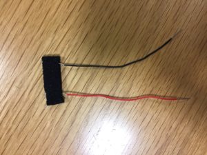
The first step was to create the pressure pad. I researched online some ways that I would be able to do this. On Youtube I found a couple of different ways, one of them was through some conductive foam:
This way did not work as I had hoped, the electricity would only conduct when the foam was pressed with extreme pressure and due to the nature of the foam the input values changed too much. The values were also at a great range so smoothing them out would not solve the problem so easily.
I then found a tutorial for making a pressure pad, the concept was simple enough and thus I made a prototype:
Unfortunately this ended up being a mere switch which is not what I wanted.
Lastly, I chose to use a pressure switch. At first I avoided this due to the size. It was too small for the idea that I originally had in mind. However, I was able to solve it by creating a platform that would concentrate all of its forces on one spot.
For the sound I was able to rent an mp3 shield. I soldered the shield and with the patience and help from Adham I was able to download the mp3 sound I wanted and programmed the redBoard to trigger the sound when the input from the pressure sensor changed by a factor or 10.
The physical box I created was designed using illustrator and laser cut. I believe the material is plywood. I regret not measuring the thickness of the wood as the wrong measurements destroyed the aesthetics of the box. I originally wanted to add springs in order to give the platform some give. However, I could not locate any and came up with a better solution. I decided to stable pieces of stretchy fabric to the bottom of the wood base.
Originally I planned on making the box bottomless, however due to the sensitivity of the sensor I had to cut out a loose bottom to make sure that I could open it and plug things in as well.
So, I had the inital idea of making a wall clock that detects when a person is looking at it and if the person is, then the clock would function normally but as soon as he/she looks away it would go haywire and start moving around.
This proved to be difficult to implement as it is almost impossible to detect a person looking at the clock with simple sensors and without using some sort of computer vision. Therefore, I turned to the next best thing with the advice from our professor: A wristwatch which detected to tilt movement as you read the watch.
I used a servo coupled with a tilt sensor and some code to make it work.
Here is a video of it working:
Here’s the code I used:
#include <Servo.h>

Servo myClockServo;
int pos = 0;
int lightSensor = A0;
int tiltPin=2;
int maxLight=0;
int reading;
int previous = LOW;
long time = 0;
long debounce = 50;


void setup()
{
  pinMode(tiltPin,INPUT);
  digitalWrite(tiltPin,HIGH);
  myClockServo.attach(9);
  Serial.begin(9600);
}

void loop()
{
  boolean crazy=false;

    int switchstate;
    int inPin=tiltPin;
    reading = digitalRead(inPin);
    if (reading != previous) {

    time = millis();
  }

    if ((millis() - time) > debounce) {
     switchstate = reading;
    if (switchstate == HIGH)
      crazy = false;
    else
      crazy = true;
  }
  previous = reading;


    int delayVal=10;

    if(crazy){
      myClockServo.write(101);


      } else {

        myClockServo.write(180);
      delay(500);
      myClockServo.write(0);
      delay(500);
        }


}
For the stupid pet trick, I wanted to design a child’s nightlamp that would change into different colors when the child tapped it. Not only that, but I thought it would be fun if the lamp was able to move slowly/have some kind of motion as it shun its light in the night.
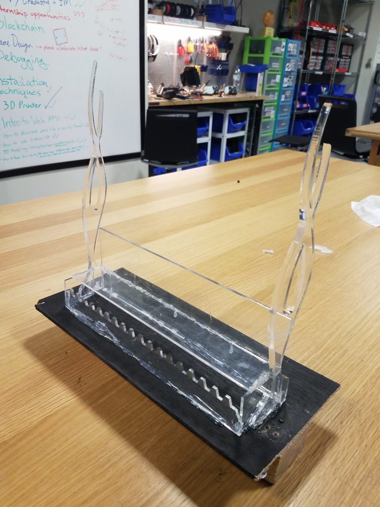
Therefore, my nightlight came into fruition with the help of neopixels, a stepper motor, the laser cutter, and the 3D printer.
First I built the base using the laser cutter and acrylic.
The side pieces were found in the junk shelf so they are not included in the schematic.
I knew I wanted 2 different kinds of neopixel patterns, so there were neopixels strung to the top of the lamp with orbs from the 3D printer.
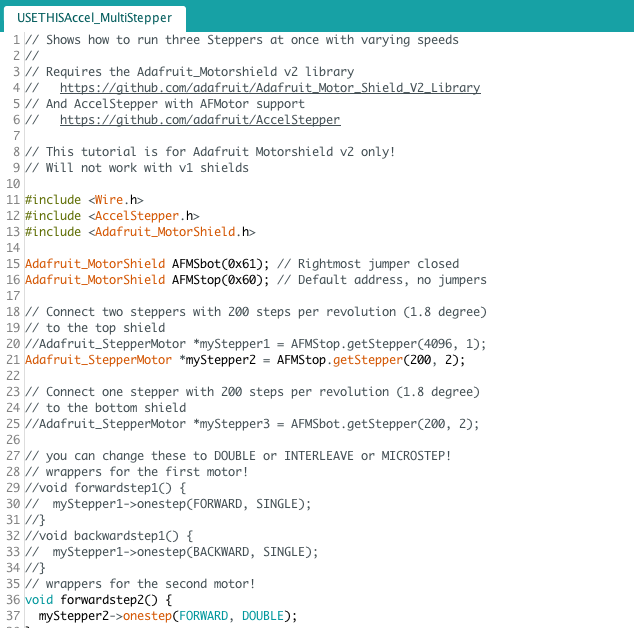
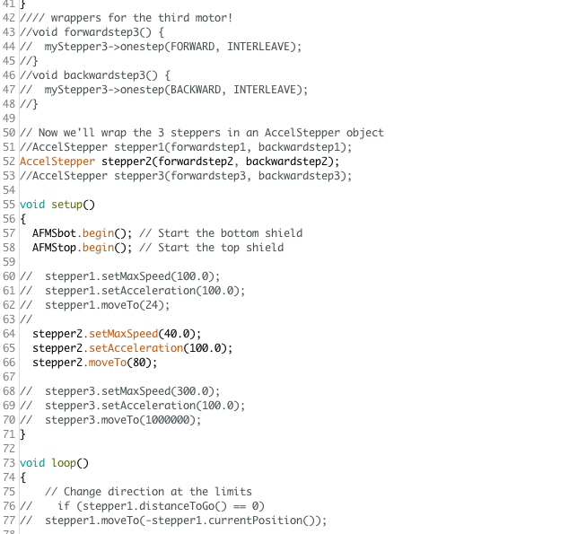
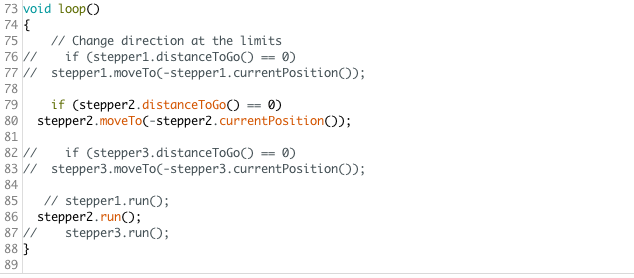
Then there was the rack and pinion which physically moved the motor after neopixels were attached to it. The motor was attached to an arduino using a motor shield. Here is the code for the neopixels.
Stepper Motor:
And finally here is the end product. There is a touch potentiometer that allows for the neopixels to change in color.
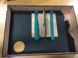
For midterm project, my original idea is to make a mystery box that blows bubbles at you upon opening the lid. However, due to various technical problems and time constrains, that idea was not realized. On the other hand, it is very satisfying to see the three motors at work and how bubbles are produced. The system consists of two servo motors that acts as a mechanical arm that dips the slotted spoon in the soap water and then hold the spoon on top of the fan. Also, a dc motor that works as a fan that blows the bubbles.
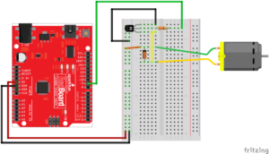
I spent a lot of time building the circuit and debugging my code. I did not know that I need a diode in order for the dc motor to work. Even though my entire circuit worked fine for a couple of hours, my dc motor stopped working at some point. I suspect that the absence of a diode also damaged my transistor. As a result, I had to replace the motor and transistor and rewire my my circuit connected to the dc motor according to following graph:
Another difficulties I encountered was to set the delays for the movements of my servo motors. Since delay() function would stop the whole system and it would not respond to user input during delay period, I have to come up with an alternative. So I used millis() function instead:
[code]
#include <Servo.h>
Servo myservoBot;
Servo myservoTop;
int photocellPin = A1;
int photocellReading;
const int gearPin = 2;
int servoAngle = 0;
unsigned long previousMillis = 0;
//
// Serial.print(“Analog reading = “);
// Serial.println(photocellReading); // the raw analog reading
}
[/code]
I was going to set up a button/photo censor that would be able to stop or start the sequence of motion of the machine. This could be used to mimic any user input (i.e. opening box). Nevertheless, this feature can be added in the future when I improve on this project.


 Then there was the rack and pinion which physically moved the motor after neopixels were attached to it. The motor was attached to an arduino using a motor shield.
 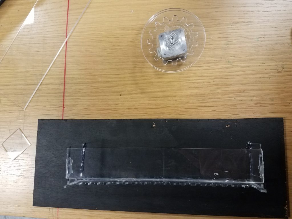 Here is the code for the neopixels.