Without a decent idea and having wasted a lot of time messing around with a handful of different motors, I decided to go on a little getaway to Yas Mall with Ross. As we stopped by Daiso to pick up some bubble solution, I spotted this little solar-panel-powered-plastic-plant (SPPPP) with leaves that would bob up and down if given a strong enough light source. I figured then and there that I could perhaps create some sort mechanical plant that would simulate the behavior of the actual plant. The sunflower and it’s tendency to follow the sun throughout the day seemed like as good a choice as any.
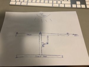
I began by mapping out the algorithm and writing it into code. The logic behind my device was basically just calculating the difference between the values from the two LDRs placed on two opposing ends of my panel and tilting the panel towards either end based on the value and the sign of the difference.
My code:
#include <Servo.h>
Servo myServo;
const int servoPin = 5;
const int photoResistor1 = A0;
const int photoResistor2 = A1;
int prReading1;
int prReading2;
int readingDiff;
int servoPos = 90;
void setup() {
// put your setup code here, to run once:
myServo.attach(servoPin);
Serial.begin(9600);
}
void loop() {
// put your main code here, to run repeatedly:
prReading1 = (analogRead(photoResistor1) + 79);
Serial.print(prReading1);
Serial.print(” “);
prReading2 = analogRead(photoResistor2);
Serial.println(prReading2);
readingDiff = prReading1 – prReading2;
// if light is very dim, return to starting position.
if (prReading1 < 30 && prReading2 < 30){
servoPos = 180;
myServo.write(servoPos);
}
// when reader1 > reader2
if (readingDiff > 10){
if (servoPos <= 180){
servoPos++;
myServo.write(servoPos);
}
}
// when reader1 < reader2
if (readingDiff < -10){
if (servoPos >= 0){
servoPos–;
myServo.write(servoPos);
}
}
}
With the code completed, I built a prototype out of cardboard (stand, panel, servo arm) and wire (pivot, axel). The design was sound until when I had to figure out how to replicate it with acrylic/wood. The pivot made out of wire no longer worked as it did with cardboard since acrylic is a much harder and solid material that simply did not allow the kind of penetration that cardboard did. I ended up redesigning the pivot/axel by laser cutting out holes in the panel and stand and installing a bolt/screw as the axel.
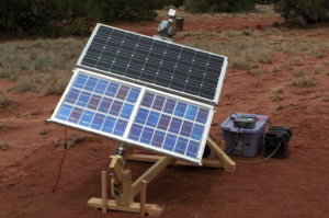
After putting the device together, I realized that the white acrylic panels coupled with the metallic bolt/screw were actually very aesthetically pleasing. Instead of covering it with sunflower decal, I decided to just leave it as it is. A practical implementation for this device could be to enable solar panels to turn and face the sun throughout the entire day, maximizing the amount of energy it could harvest.
The following video is a demonstration of the device in action:
The idea of my project derived from my strange tissue obsession. The concept was that every-time I would want to reach for the tissue box, it would move further away. I planned to achieve this using a photo sensor. While it moved away it would create a sneezing sound.
I started off with experimenting with the servos. Initially, Aaron told me that a student had done a similar idea and made the object ‘jump’ somehow. I had a difficult time creatively thinking about how to make the tissue box jump through the smaller servos we got in our Red SparkFun boxes. I couldn’t think of any mechanism to make the tissue box jump. Subsequently, I started looking at other servos in the lab and came across the continuous rotating servos, and found wheels that go along with it.
My plan was to put these two wheels alongside the tissue box. After consulting with Aaron about this idea, he said it would be better if I incorporated something within the tissue box, as putting wheels outside the tissue box would make the pet trick appear to obvious. Overall, it would defeat the purpose of a pet trick. I decided to put one wheel inside the tissue box.
The challenging part about putting one wheel inside was that the weight was unevenly distributed, and the tissue box was elevated slightly, making one side lean towards the ground more than the other. When the tissue box would move, it would curve and not move in a straight line. I added a layer of cardboard to slightly even out the tissue box. If I had more time, I would incorporate small, rubber lego-tires on the bottom of the tissue box so the weight is not unevenly distributed and can move in a linear path rather than a curved one.
One of the most challenging parts of the project was coding the box to move back to its original position. Every time I attempted to create the timer or set the appropriate booleans to activate whether the box moves away/comes back, something went wrong with the code. Aaron really helped me get a better understanding of the logic behind the code. Two really important takeaways from this process was that 1) Instead of trying to write code directly on the application, it’s better to take a piece of paper and understand the logic behind it first, and 2) Always check your code step by step instead of all in one go (which is usually what I do). It only becomes more challenging to debug it that way.
Another challenge was trying to add the sound effect. I used an Arduino Due and Wifi Shield. I looked at various demos online, however one of the necessary import libraries was not working, which wouldn’t allow the audio to work. I tried using other materials from the lab, such as the AUX jack breakout, but there was limited information on how to use them with the combination of materials I had. My last option was to directly connect the speaker to the board, but I had read controversial reviews on how that could be dangerous so I chose not to for the efficiency of the board. I was quite disappointed that I couldn’t use the audio as I felt that it would have added a great touch to the piece. I used an LED as a substitute, signalling a red light every-time one tried to reach for the tissue box as a warning symbol. It wasn’t the best alternative. If I could get a hold of an MP3 shield next time, I would definitely add audio to my project.
*Note: I do plan on adding audio to my project on Monday/Tues (Mar 5/6. 2018), once I am done a couple of other important assignments over the weekend.
Initially at a loss for what to do in the class discussion the idea of making some sort of rube-goldberg-esque ball game came up. Though it wasn’t stated at the time, some one later refered to it as inverse pinball, and that is an accurate succinct description.
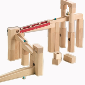
My initial idea was to have a fully 3D tower like set of paths and various controls to direct the ball along these paths, as in the image below. That type of ball-block set was the primary motivating inspiration aesthetically, even as my idea itself changed.
The first and most significant change to this idea was primarily due to the complexity of making the project I originally envisioned. While technically equivalent to the updated idea, in order to give the 3D version sufficient choices and moments of interaction be be worthwhile it would need to be large, and the additional size would require additional techniques, without displaying much additional technical prowess. Instead, I decided to make the game flat and wall mounted, and replaces the choice of paths with various pitfalls.
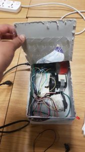
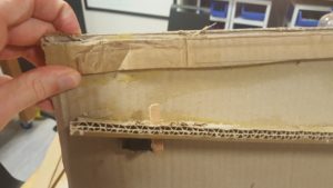
In response to this change, it made sense to use a different control mechanism. In my original concept the player would control the game using various inputs located on the game itself, many requiring physical contact. With the game now wall mounted, it no longer made sense to require the player be in such close proximity or require such precise controls. Instead, all the mechanisms are controlled by a single input, a light sensor, which is set to have a very low threshold. The following images show the game at various stages of construction, unfortunately I dissembled the electronics before collecting video documentation.
1
2
3
4
Each of the servo motors controls a flap in the path, as can be seen in picture 3. They are set so that at one of the extremes of their motion they create a smooth path, while at the other the flap is fully open. Unfortunately, during construction the cardboard lost much of its structure, and so pieces that initially would return to true now remain in the open position. In addition, there is a solenoid that if used with proper timing should propel the ball across a small gap in the path. The ball itself is a ping-pong ball wrapped in tinfoil. In the games current implementation the tinfoil serves no purpose, but mechanisms have been implemented that partially allow the result of the game (win or loss), to be displayed. The game collects this data, but does not make use of it currently.
While I am content with this project from the perspective of a proof of concept/early prototype, it is very flawed, most obviously in level design but in almost every aspect. However, I do intend on re making it, using more permanent material such as wood, implementing a scoring system, improving user interaction and accessibility, and potential adding additional features, such as markers that identify whenever the player passes each challenge. As we study using the computer to communicate with the arduino I may have additional inspiration for features, but my current visualization is intentionally minimalist.
Since I really enjoy using servos (I like them more than LEDs), I wanted to create a stupid pet trip that would at least use more than one of them. I originally just wanted to have a LDR that would basically take into the account the light levels that the plant was getting and if there weren’t enough sunlight, the servo, acting as the eyebrows of the face on the pot, would point more downwards to depict an angry/sad face – like in the image below.
But then during the class discussion, I found two other alternatives that would be cooler 1) detect the water levels of the plant and then that would trigger the servo to move, 2) anthropomorphosise the plant and have a sound detector/microphone attached that would sense that there is sound next to it so that it’ll be happy when it hears that someone is talking to it.
I started playing around with the soil moisture sensor first because I was most unfamiliar with it. After some confusion with how to connect it, I finally got it to work and tried to actually water the plant so that the soil moisture level would change. Below is a video of the serial monitor that showed the moisture level.
The code for this is shown here:
int val = 0; //value for storing moisture value
int soilPin = A0;//Declare a variable for the soil moisture sensor
int soilPower = 7;//Variable for Soil moisture Power
//Rather than powering the sensor through the 3.3V or 5V pins,
//we’ll use a digital pin to power the sensor. This will
//prevent corrosion of the sensor as it sits in the soil.
void setup()
{
Serial.begin(9600); // open serial over USB
pinMode(soilPower, OUTPUT);//Set D7 as an OUTPUT
digitalWrite(soilPower, LOW);//Set to LOW so no power is flowing through the sensor
}
void loop()
{
Serial.print(“Soil Moisture = “);
//get soil moisture value from the function below and print it
Serial.println(readSoil());
//This 1 second timefrme is used so you can test the sensor and see it change in real-time.
//For in-plant applications, you will want to take readings much less frequently.
delay(1000);//take a reading every second
}
//This is a function used to get the soil moisture content
int readSoil()
{
digitalWrite(soilPower, HIGH);//turn D7 “On”
delay(10);//wait 10 milliseconds
val = analogRead(soilPin);//Read the SIG value form sensor
digitalWrite(soilPower, LOW);//turn D7 “Off”
return val;//send current moisture value
}
After making sure that I knew how to work the soil moisture sensor, I moved on to programming my servos. At this point, I realised that it would be a lot more fun if the servos could react to sound (as in cooler and more different for the final product). I, therefore, decided to move towards using the sound detector sensor. Like the soil moisture sensor, I had to figure out how to connect the wires and where to solder headers and what not.
After making sure that it works, I tried to programme the servos so that they would react to changes in the sound detector. This process took me many many hours because I couldn’t figure out why, even if there were no sound, the sound detector would detect that there is a sound and so the servo would be in a constant movement phase where there would be no time that it was not moving. Using the serial monitor, I realised that it was in a constant loop of “quiet” and “loud”.
Messing around with the code, I realised that I couldn’t tell the servo to move 0, 90, or 180 degrees or it would malfunction, I could only use numbers that were not those 3. I still don’t understand why that is, but my code worked after that. The video for that is shown before.
It was then time for me to make the actual hardware part in order to show what I wanted to do with the eyebrows for the plant pot. After measuring where the servos would be located in the pot, I drilled 2 holes into the side of the pot where they would stick out. I realised that the “head” of the servo was too short to extend to the outside of the pot so I attached two small pieces of some plastic straws to the tip of the servo. After that, I messed around with the angles that the servos should turn in so that the eyebrows would move in the direction that I want them to move in.
Making sure that the angles were okay, I then glued two pieces of popsicle sticks to the straws so that the eyebrows would actually be attached to the servos. I then gave the pot 2 eyes and a mouth.
I put a flat layer of hard styrofoam on top of the servos and placed a real plant on the top so that the fake pot could actually do something in useful terms – have a real plant so that the whole point of the project would work.
I then decided to test the project out. The video of my final project in action is shown below:
And here’s my plant, Mr. Greenie McGreen reacting to Adele’s “Hello” because why not.
So yea, I didn’t end up using the moisture sensor- but at least I know how it works now!
Also, I originally wanted to make it so that the faces would change from a angry/sad face to a happy face but the shocked face worked out better because then it would just recognise that someone was talking to it and if someone were to swear at it *ahem Adham*, it would show a shocked face and not a happy face. So, I guess it worked out!
NOTE: I basically created the base in which you put your plant pot onto, not the plant itself.
Touch screens are actually great — for now. They facilitate for immediate, responsive, and efficient interactions with our smart phones. In recent years, companies have been trying to move towards voice control as an alternative/supplemental mode of input. Though the technology has been available for years, voice control still does not feel as convenient, efficient, and useful compared to touch screens. Sure, it’s lovely to be able to holler at Siri and ask her to read you your notifications while you’re in the shower. However, I still do not see voice control becoming something that users could fully integrate and replace touch gestures with. For one thing, it’s definitely not as discrete/private as touch and that would be a problem when in the public. Until the next great interactive technological advancement takes place, the touch screen is probably the best option we have.
The future depicted in the video is cool, but not because of the technology exhibited in it. What attracted me the most was the bezel-less, minimalistic, ultra-modern design, which I found very aesthetically pleasing. I strongly agree with the author on the observation that the featured technology really is a rather small increment in the functionality department. The design makes everything look fresh and much more interesting, but if you look closely, we’re essentially doing the exact same thing we’ve been doing all this time. Victor’s analysis on how we should pay more attention to our humanly capabilities (maybe other than our hands) and go on from there is definitely a good start. Perhaps one day in the near future, our “smart phones” would cease to be handheld devices. Perhaps the display and controls could be seamlessly integrated into our natural vision via high tech contacts — just like those featured in season 1 episode 3 of the Black Mirror.
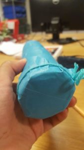
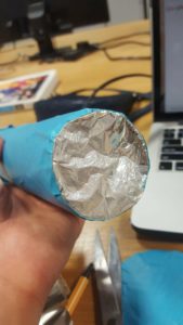
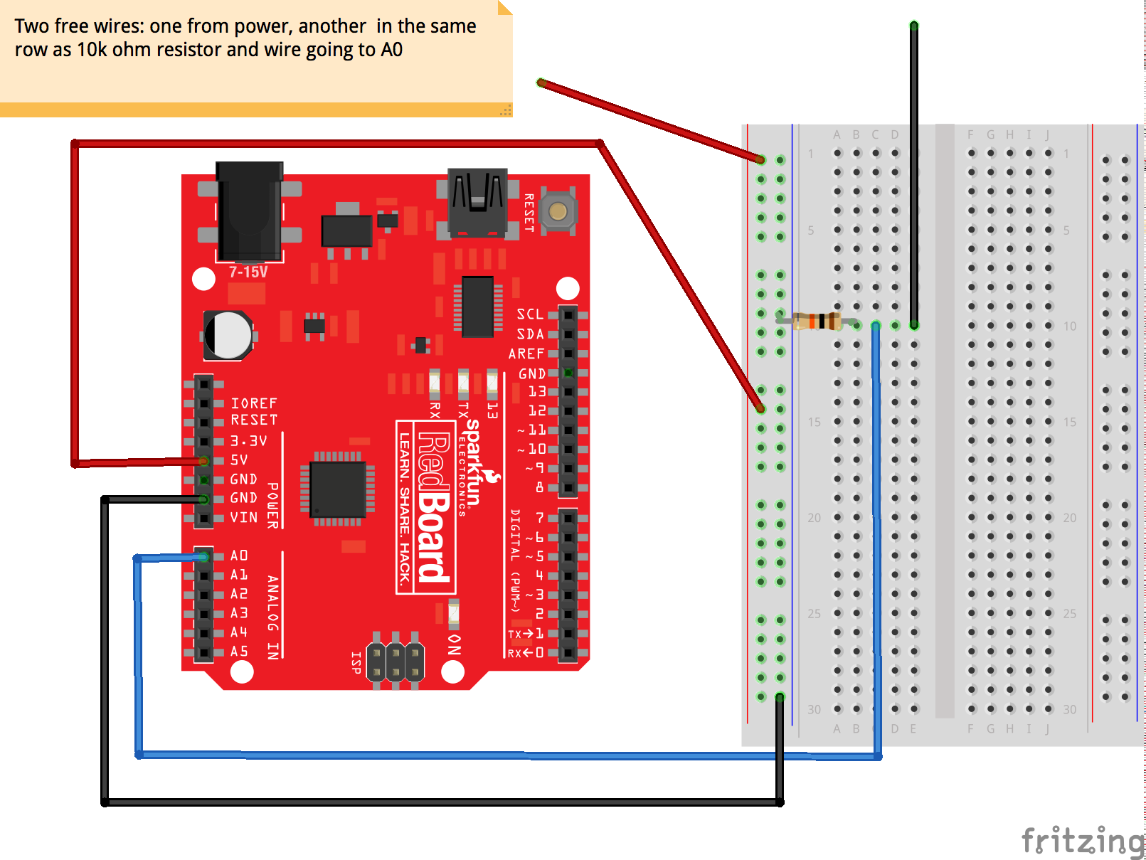
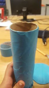
We attached to toilet paper rolls together. Initially, we use tape to cover the open ends of the roll. However, that didn’t emphasise the sound clearly. It sounded quite dull when he aluminium balls hit the surface of the tape. So we ended up using aluminium to emphasise the sound further. We created a stand rainstick, however the weight of the rainstick was heavier than the stand, so we needed a platform, some sort of rectangular structure and weight in the empty space to balance the overall weight of the structure.
Tissue paper rolls 2. Creating the “drum-skin” for the rainstick
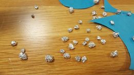
3. Rolled aluminium pieces to create rain-drop effect
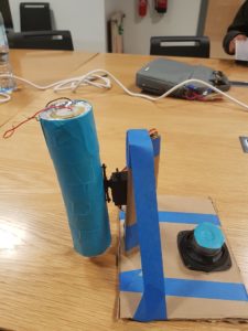
4. Final Structure
Ways of improving the project:
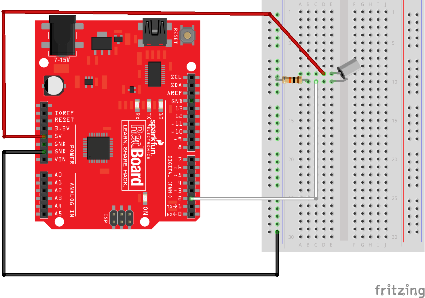
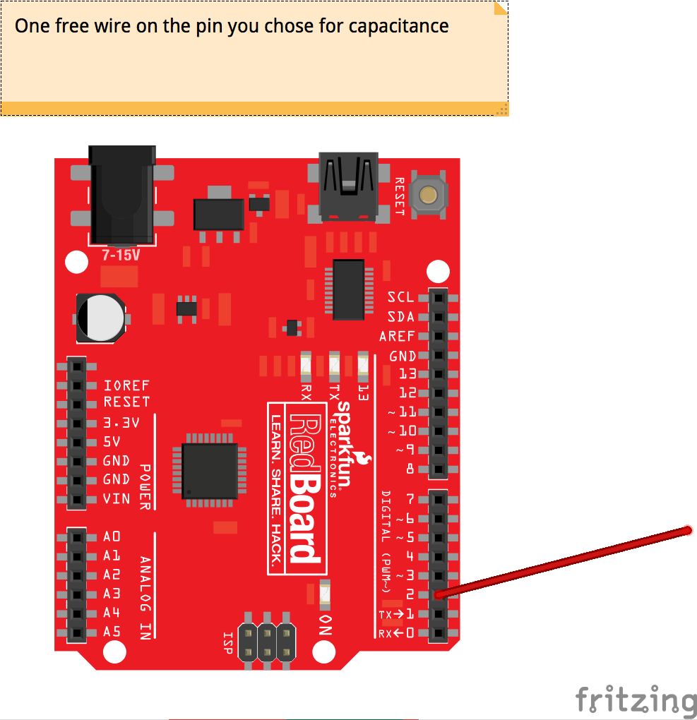
We attached a piezo element to one end of the rain stick to complements the sound of the rain stick. Ideally the piezo element would have reverberated with the end cap to turn the entire rain stick into a resonance chamber, but we could not get the aluminum sufficiently tight.
We used the example code for the servo, modified to pause at each end and allow the rain stick to come to equilibrium. Ideally we would have rungs throughout the rain stick to increase the noise it makes, but they are not present in this version.
The musical melody was made extremely last minute, and it was quite upbeat. It did not provide the relaxing tone needed for an effective soundscape. Next time, ideally we would spend more time focusing on the quality of the musical piece to genuinely resemble an accurate sleep soundscape.
Before reading the post, my initial response to the video was being thrilled for the technological advancement to come and curious to see how it will change the everyday lives of people. However, reading the first few paragraphs reminded me of an opinion I have consistently held for a few years – I often times do not appreciate touch screens. Here are a few anecdotes that describe my past experience with touch screens: I got rid of my first touch-screen phone because I could not deal with not being able to text without looking at the keyboard on the screen; I got rid of my iPad because I lacked the patience it takes to type on the screen with the keyboard covering half of the screen; I got rid of my ebook reader because swiping to flip over the page just felt wrong. Remembering my history with touch screens made me wonder why my initial response was excitement for future interaction with a whole lot of touch screens.
The commonality of the touch screens that I disliked is the fact that I was unable to use my fingers to figure out where to place the finger movement to induce the intended reaction. To be more specific, a touch screen lacks the physical difference in the sense of touch of a key that a user wants to press, a key one does not wish to press and the gap between two different keys. In other words, the user will not know whether one was successful in entering an item until the item is printed on the screen. This means the user has to fix one’s eyes on the screen for at least two reasons: 1. To locate where the key the user wants to press is; 2. To make sure that the user has not made a typo. The problem of having to rely solely on vision could be a critical limitation for individuals with visual impairment using touch screen devices. It could be said that, a touch screen can, unnecessarily, eliminate the sensory information effortlessly collected by the fingers and increase the need for visual information, leading to an overall increase in the attention required for operation.
Despite everything I have said, I don’t mean to say that touch screens are bad – iPhone good.

 1
1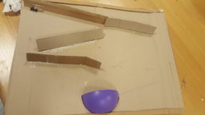 2
2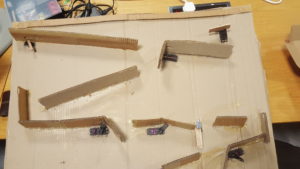 3
3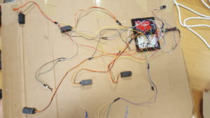 4
4
 2. Creating the “drum-skin” for the rainstick