There Are No Electrons – Response

Frankly, as someone whose experience with Physics ended more than two years ago, I was glad that I wasn’t asked to read 40 pages packed with technical information about physics. After reading the ‘About This Book’ page, I became curious to find out why this book was rejected so many times that the author had to start his own publishing house to get this published.

A few pages into the reading, when I read how he explains what a jargon is, I thought it would be nice if my 13-year-old brother read this. Also, I felt that this was much better to read at 7am than the Genocide Convention. However, when I realised that it took 18 pages to introduce the concept of electron, proton and charges, I began to think that I might be wasting my time. As the knowledge couldn’t be separated from the stories and analogies, I ended up reading the entire page, only to find Amdahl say “You don’t need to know any of this to study electricity. I just thought it was interesting.” – I felt almost betrayed.

Although it did not provide me the amount of knowledge I had expected, I still think Amdahl’s attempt to write a book that allows people to learn without effort was meaningful. Reading it really did not require much cognitive activity other than making sure that my eyes stay on the page and it may be suitable for a different readership.

After all, he did say “Don’t mistake your watermelon for the universe” so I would like to think that it’s the thought that counts.

Week 1 project

For this assignment (to make a switch that works without using hands) I quickly came upon the idea of using breath, specifically blowing on a piece of tinfoil. Luckily, I found that if a bent a piece of tinfoil at about a right angle and blew on it it would change the angle and then return back to the bent position. After some initial testing that holding the two wire ends and blowing the tinfoil into them would complete the circuit, I built a small frame to hold it all together. I took a piece of cardboard and affixed a section of tinfoil to it, and then bent the tinfoil at a smaller angle so that it was about an inch above the cardboard. I then poked two holes through the cardboard, and pushed the wire ends through these holes so that their ends extended about a half inch past the cardboard.

There Are No Electrons Response

I strongly disliked this weeks reading, There Are No Electrons. The author, Kenn Amdahl, begins the book by explaining how he wanted to create a more engaging, memorable textbook by adopting narrative strategies from the likes of Star Wars. This concept, while admirable and even seemingly promising in theory, is executed poorly through the remainder of the assigned chapters. Amdahl constructs a series of long-winded, broken analogies for electrical concepts, centered around the fictional Greenies — small, green humanoids with a love for concerts and parties which drives them into stampedes which power our electrical devices. Most of the content of these stories is absolutely unnecessary, and fails to add any interest to the concepts that Amdahl is trying to convey. Where a simple analogy to a ball rolling down a hill would suffice, he provides a long story about Chuck Berry, rock concerts, and the “need-to-party”. Worse, his focus on disputing electron theory often distracts from the concepts he is trying to express, and is founded on shaky arguments. Near the end of the passage, he claims that he wrote the book because he couldn’t get a current to flow between two batteries. In other places, he seems to criticize parts of electron theory for being unintuitive. His comparison between modern science and the Spanish Inquisition also seems to discount the vast amount of experimental data which has thus far shown to be remarkably consistent with current theories and forms the basis for any belief in them.

There are no electrons

I found the excerpt an interesting read and there is definitely a lot one can learn about electricity. The analogies and humorous tone such as questioning why the farmers in Greece would want to rub their sheep with pieces of amber in the first place makes it much more interesting.

The book is targeted towards the younger audience as it creates an atmosphere that would allow children to enjoy the book and this is what the author wants. However, it seems to be targeting the more younger children rather than the preteen/teen age children which I think is not enough to really create an impact in educating the youth about electricity and giving them a better understanding of it.

I’m going to massage your back.

Well, my initial idea was to make a glove trigger so that when you clench your fists, something will switch on. So I just connected the motor that was given in our sparkfun kit to the redboard and switched it on. It wasn’t staying still for the movement, so I put two regiform pieces on the side of it to keep it stable. Switching it on, I then realized what a good massager this was. Playing with it for a while, I changed my idea from an, “Iron Man” type glove trigger to a back massager. This is what my initial prototype looked like:

The hanger would aid in keeping it stable on the chair like this:

I had to find a way to cover the motor so that people don’t get their backs drilled instead of massaged so I did this:

Here’s a video to demonstrate the amount of vibration it makes.

I needed a method to make it switch on when someone lied on their back in the chair so I made this with some foil that connected the wires to the motor:

And now, the final product on the chair:

Punch Your Lights “On”

Brainstorming and Design

When we were first assigned this project, I knew I wanted to have a play on words. Since the assignment required that we not use our hands to activate the light, my first idea was to have a pair of handcuffs used in order to complete the circuit and light the LED, but I thought that idea was too simple. (I also could not procure a pair of handcuffs in time for the assignment)

And so my next idea sprung from the phrase “Punch your lights out.” I figured I could do a play on words by activating an LED light by doing a punching motion.

And so my idea was born.

Above you can see my sketches for the design. It was a bit Spiderman inspired, as I knew I wanted a gadget specifically on the wrist that would activate the light by doing a punching motion; this is similar to Spiderman’s flicking motion in order to make web shoot out.

Building Process

The final product should be placed on a strap to wear and then it is complete.
Completed Circuit

Final Product

Here you can see a completed product being used in order to light the LED.

IM Punch Light

Pressure Sensor

For the first week’s homework assignment, I decided I wanted to build a switch that could be used in a variety of ways. Although the examples that we examined in class, such as the mustache switch, were creative,  they seemed rather limited  and required very precise conditions to operate. In addition, I felt that simply modifying previous examples by simply using a different body part to activate the switch seemed unoriginal. This left me with two primary paths to explore for this project.

  1. Create a switch that is powered something other than human interaction (e.g. wind, heat, water, etc.).
  2. Create a more general purpose switch which can be powered by a variety of sources.

I ended up choosing the second of these options, as it opened a broader array of possibilities for interaction, and seemed more conducive to creating a reliable device that wasn’t limited to very narrow parameters.

Following this path, I decided to build a pressure sensor, which would activate a light when pressed down upon. To test the idea, I placed two pieces of copper tape, each connected to a wire, on opposite sides of a piece of fabric containing a hole in the middle. When the wires were pressed, the two strips of copper tape would touch, completing a circuit. When they were released, the switch would open, breaking the circuit.

This early version had several issues, however. The fabric had to be pressed together in a specific place to close the circuit, making it difficult to turn on the light by simply placing an object on top of the switch. To solve this, I built a enclosure around the switch using two pieces of wood that I found in the lab, as well as several pieces of foam. When pressed, the foam compressed and the top piece of wood came into contact with the fabric, activating the switch. However, I found it difficult to keep the wires of the circuit connected to the copper tape in the switch.

To fix this, I built one final version, using metal buttons to clamp the copper tape, fabric, and wires together. I also replaced the wood enclosure with new laser-cut wood parts, and added shrink wrap to make the wires neater.

Final Product

Maze Project

For this project, I decided to build a maze that activated the LED light when the ball reached the end of the maze.

I started by building the maze out of a cardboard box:


I then needed to figure out how I would be able to get two pieces of aluminum foil to hit into each other. At first, I thought I would be able to get the ball to hit into one standing piece of aluminum foil so that it would then hit the next piece of aluminum, where the contact of the two pieces would serve as a switch and activate the light. However, I couldn’t manage to find a way to do that while also having the aluminum attached to the wires because I was thinking of the contact like having a dominos effect.

I then decided to try and see whether I could have the ball be the medium of contact by covering it in aluminum and then having it touch a piece of aluminum at the end of the maze which would activate the switch. Again, the issue of wires came up, where having the wire attached to the ball wasn’t feasible and would get in the way of the game.

I then decided that perhaps the best was to have the ball press down on a piece of aluminum to achieve contact. I decided to test whether putting two pieces of cardboard (covered in aluminum) in a sea-saw shape would be able to work. It managed to work and so I then tested whether the balls weight was enough to push down the top piece of cardboard. This idea worked! I then glued the bottom piece of aluminum to the end of the maze, and connected the wires through the sides of the cardboard.

Here are some pictures of the final product:

Project 1 – The AnyBall game

Upon receiving the instructions to make this project I knew that I wanted to make a game. My general idea was to make a game which would signal when a ball hit the assigned space. The assigned surface would be a kind of sandwich containing 2-3 layers. The first layer (bottom) would be cardboard to contrast from the rest of the ‘game board’, the second aluminum for conductivity and the third a flexible conductive fabric that a ball would hit. The circuit for the LED would be complete when the aluminium and upper layer connect. I began by making a few sketches: 
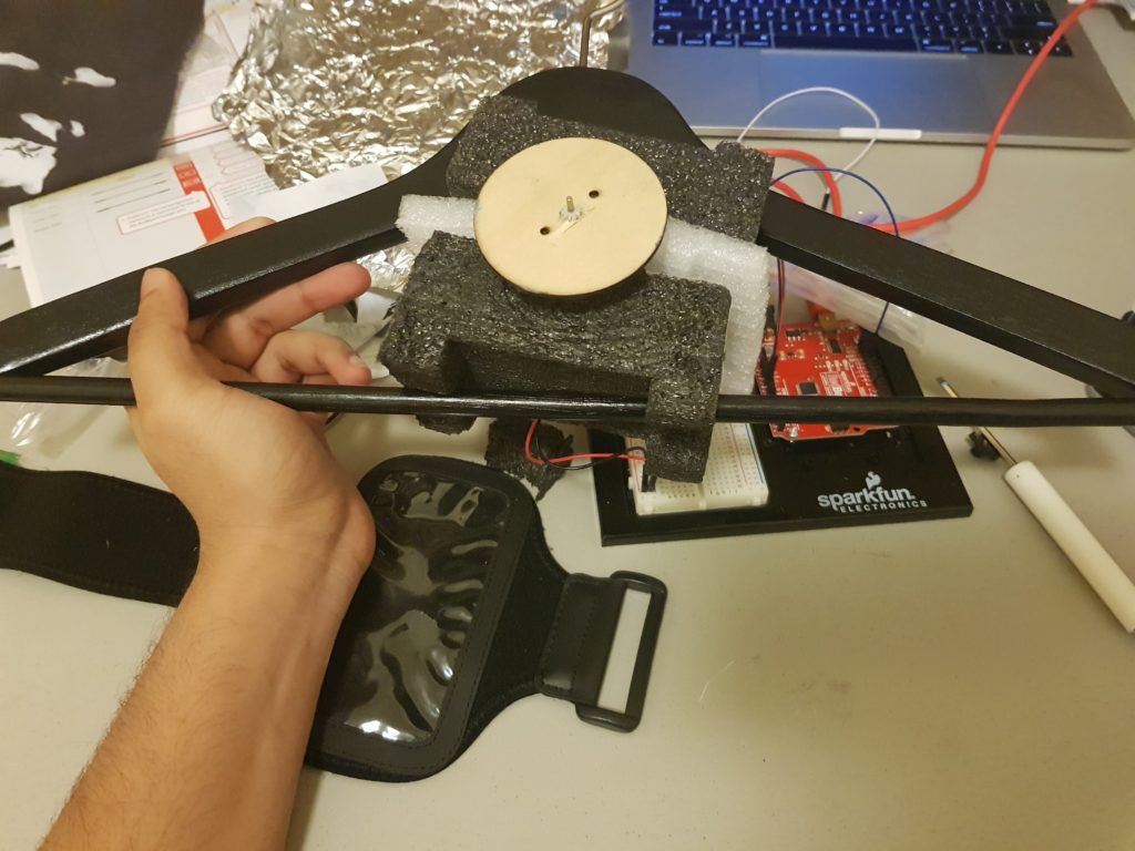
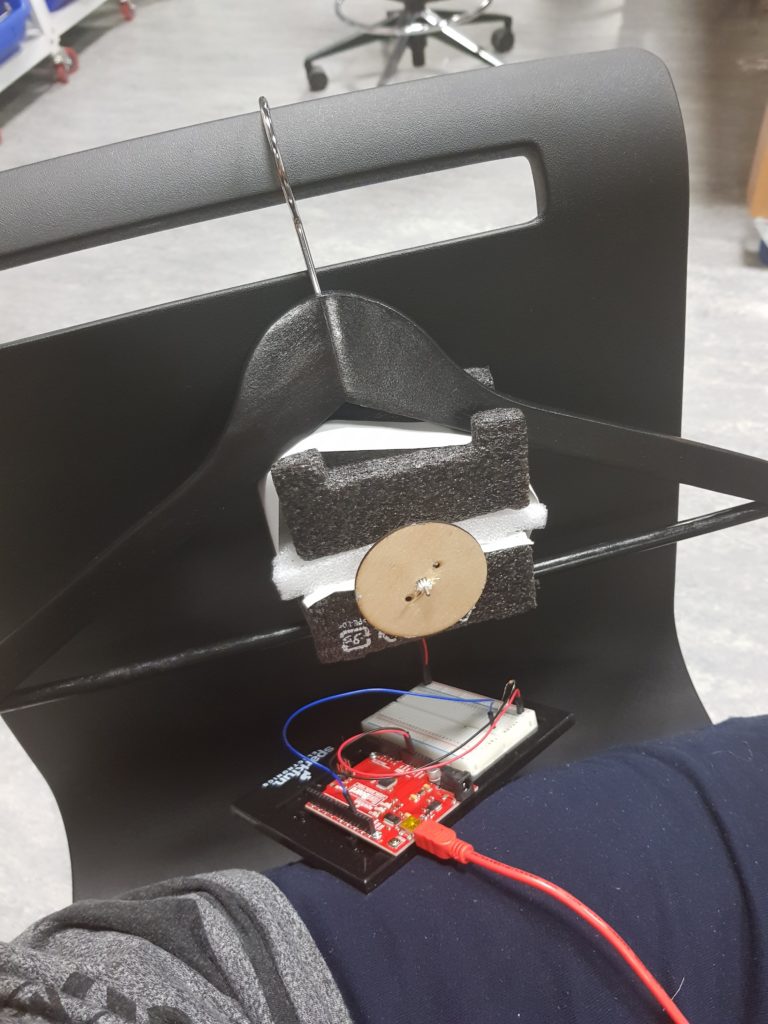
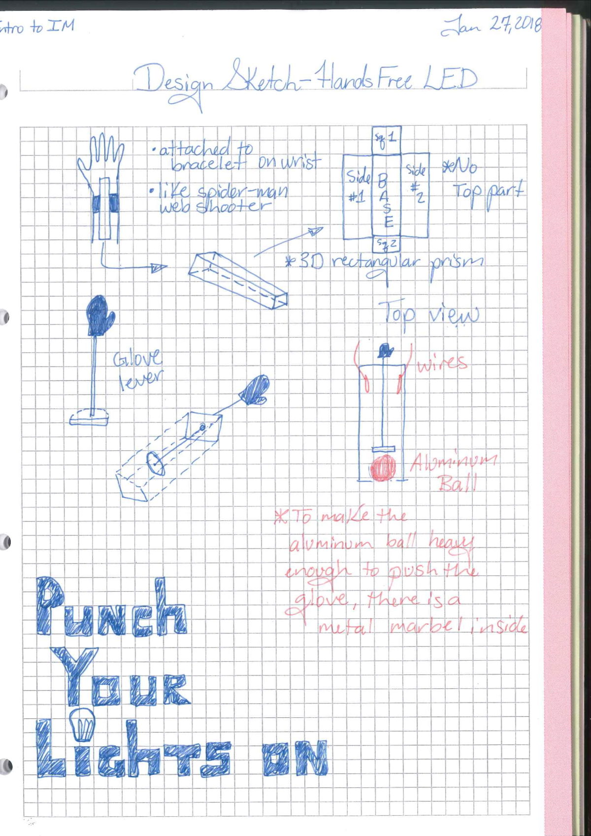
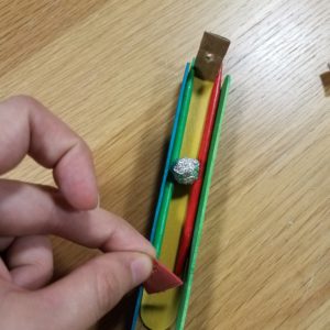
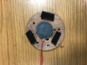
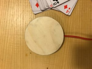
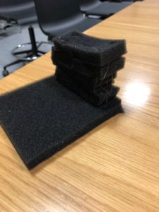
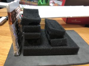
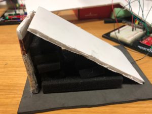
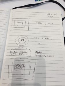
There were a couple of designs that I thought of. One of the ideas consisted of circles but I decided against it because it would logistically be a hassle. Using a square or rectangle would work just as well and without the trouble.

The box itself is cardboard as it is inexpensive and easy to use. I began to make the box by designing it using Adobe Illustrator. After making the design, I used the laser cutter to make the box parts.

Next I spray painted all the parts to make it more aesthetically pleasing. Silver was the only paint available to me.

After doing this, I tested some fabrics for the upper layer of the sandwich. Upon testing some, I decided on chicken wire as it was both flexible and the most conductive. After choosing chicken wire, I also lined the bottom of the assigned space square with aluminium. 
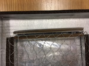
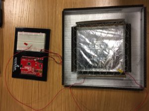
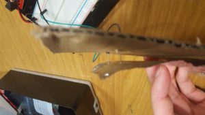
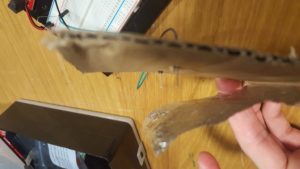
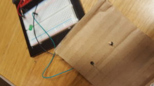
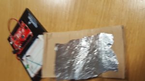
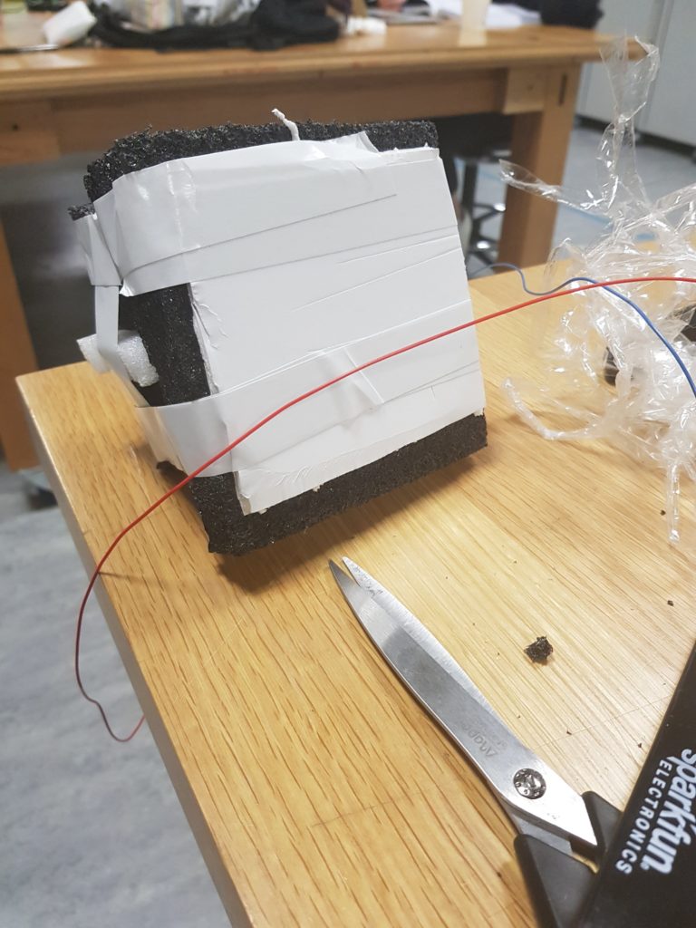
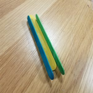
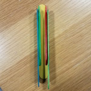
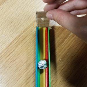
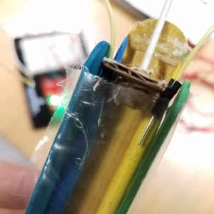
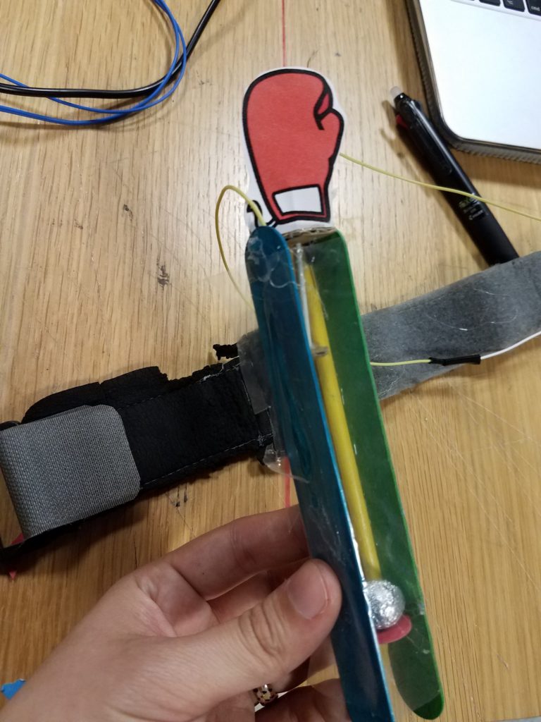
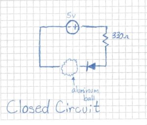
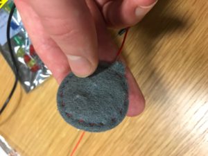
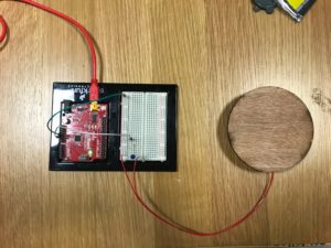
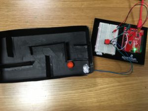
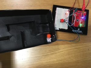
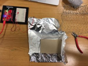
After making sure the LED turns on, I cut and taped some wire to both the aluminum and chicken wire. I put all of the parts together using hot glue.

It is aesthetically displeasing but I could not use electrical tape as it would not hold the chicken wire.

Upon finishing the construction, I wired all of the parts together. This is a picture of the final product:


Create Some Ambiance Whilst You Play the Drums?

Perhaps one way in which drumming could become more fun is to provide some lights to accompany the beat. That was the intention of my project. I decided to make a foot pedal that would make lights go on when pressed down.

After scavenging in the junk shelf, I started off with gathering some sponges that would allow for not only the compression part during the pressing down of the pedal but also allow for pedal board to bounce back.

Figure 1: Example of How I Arranged the Sponges

I then glued the sponges onto a padding that had a surface that had more grip to allow the structure not to slide during the stepping of the pedal.

Figure 2: The Arrangements of Sponges on the Surface with More Grip

I decided that the easiest way for me to create a pedal that would switch on the lights when pressed on is when, when the pedal is in neutral position, there is nothing there to conduct electricity. I realised that for me to have a surface that had a section that could be an insulator and a larger section that would act as a conductor, I would need to use something like a styrofoam board where I would cover the larger section with a conductor. I marked 1.5 cm off the top of a styrofoam board and covered the larger section with aluminium foil. To make sure it stays and to cover with another layer of conductor, I applied some copper tape on top of the aluminium.

Figure 3: Aluminium Foil and Copper Tape on Styrofoam Board

I then stuck the board onto the grip surface like Figure 4 shows below.

Figure 4

For the circuit and the switch to work, I needed to stick a piece of wire to the back of the board of the pedal so that when stepped on, the tip of the wire would connect with the conductive elements of the backboard as seen in figure 3 and 4. Figure 5 below shows this process.

Figure 5: Wire behind the board of the “pedal”

Figure 6 shows the side view after sticking the pedal board onto the grip surface. I made sure to leave some space between the backboard and the pedal board so that when stepped on, the surfaces wouldn’t get stuck as easily.

Figure 6

Figure 7 shows the final result of the pedal. I cut out some more styrofoam boards to fit onto the two sides so that the sponges inside are enclosed and so that the overall look of the pedal is more structured. As well, not pictured here, but one more wire was taped to the back of the backboard so that the circuit is closed.

Figure 7

The finished product is shown in the video below! Now you can have lights to accompany your drum beat!

Ivory’s Pedal Lights


P.S. Not seen in the pictures but I made sure to measure the dimensions of the styrofoam boards so that they would piece together nicely. The gluing together of the boards and of the sponges were done through the use of a hot glue gun.