“It means that each performance of such music piece is unique, as interesting to its composer as to others listening” — John Cage
I enjoyed his talk primarily because I got the chance to see so many different projects using the same concept of balancing chaos and order in coding. The biggest takeaway I had was how certain controlled randomness can make a project predictably unpredictable. I will certainly use this concept in my own project this coming weekend.
I was particularly intrigued by the grid project, in which each dot on the grid is off by an arbitrary amount of pixels. But at what point does the grid stop being a grid? At what point does the randomness outweighs the order and render the whole thing complete chaos and useless? All of this are very subjective and even the randomness can tell a lot about the designer him/herself
For this project I wanted an icon that represent me rather than a detailed drawing of myself. I was inspired by a cool project I found online:https://www.openprocessing.org/sketch/7639#
I hope that I can use this on the personal website that I am going to design for Communications Lab in the end of the semester. I have a few simple interactions: hair disappears, ear enlarges and glasses to sunglasses when hovered upon, and nose changes randomly when clicked on. Below is the code I used:
boolean hair = true;
//boolean sunGlasses = false;
int x1 = 290; //varialbes to change the mouth shape
int x2 = 325;
int counter = 0; //how many times nose is clicked
int earRadius1 = 30;
int earRadius2 = 50;
This article presents us with a list of most reoccurring themes in the field of physical computing design. Most projects can be reduced down to very simple concepts. As I read through the list, I realized that I have the knowledge to handle most of the technicalities. Therefore, a lot of emphasis should be put on how to creatively use the same old concepts to give people difference experiences.
Therefore, there is no shame in making something that has been made somewhere by someone. There is value in repeating someone else’s work and add your personal touch to it later.
“So if you’re thinking of an interactive artwork, don’t think of it like a finished painting or sculpture. Think of it more as a performance. Your audience completes the work through what they do when they see what you’ve made. ”
This part of the reading really reminded me of the essence of designing an interactive experience. I often think that once I finish a piece, the piece is finished. However, I tend to forget that the users are the ones who complete the experience. Only after observing user behaviours and getting feedback without telling the user what to do can a designer improve the art piece and the interactive experience as a whole.
My original idea is to make a walking robot or a dancing robot with two servo motors as its legs. Also, I would have two knobs that control the movement of each leg. The whole setup was not hard to make. However, it turned out much more difficult than I imagined.
My robot cannot stand the imbalance
The balance was a big problem. When one leg moves, the other leg tends to wobble, making it impossible for the robot to move forward. I then tried to walk forward with only one leg moving at a time. It is impossible to move forward without shifting the centre of gravity by adjusting the other leg. Therefore, I reglued the sticks to the sides of the paper cups and made them more stable. The following is the code I used:
#include <Servo.h>
Servo myservoL; // create servo object to control a servo
Servo myservoR;
int potpinL = A5; // analog pin used to connect the potentiometer
int potpinR = A3;
int valL; // variable to read the value from the analog pin
int valR;
void loop() {
valL = analogRead(potpinL); // reads the value of the potentiometer (value between 0 and 1023)
valL = map(valL, 0, 1023, 0, 90); // scale it to use it with the servo (value between 0 and 180)
valR = analogRead(potpinR);
valR = map(valR, 0, 1023, 0, 90);
myservoL.write(valL); // sets the servo position according to the scaled value
delay(15);
myservoR.write(valR);
delay(15); // waits for the servo to get there
}
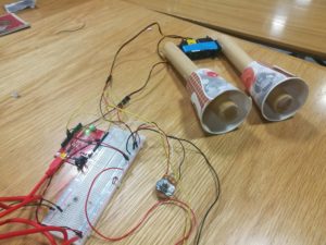
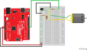
For midterm project, my original idea is to make a mystery box that blows bubbles at you upon opening the lid. However, due to various technical problems and time constrains, that idea was not realized. On the other hand, it is very satisfying to see the three motors at work and how bubbles are produced. The system consists of two servo motors that acts as a mechanical arm that dips the slotted spoon in the soap water and then hold the spoon on top of the fan. Also, a dc motor that works as a fan that blows the bubbles.
I spent a lot of time building the circuit and debugging my code. I did not know that I need a diode in order for the dc motor to work. Even though my entire circuit worked fine for a couple of hours, my dc motor stopped working at some point. I suspect that the absence of a diode also damaged my transistor. As a result, I had to replace the motor and transistor and rewire my my circuit connected to the dc motor according to following graph:
Another difficulties I encountered was to set the delays for the movements of my servo motors. Since delay() function would stop the whole system and it would not respond to user input during delay period, I have to come up with an alternative. So I used millis() function instead:
[code]
#include <Servo.h>
Servo myservoBot;
Servo myservoTop;
int photocellPin = A1;
int photocellReading;
const int gearPin = 2;
int servoAngle = 0;
unsigned long previousMillis = 0;
//
// Serial.print(“Analog reading = “);
// Serial.println(photocellReading); // the raw analog reading
}
[/code]
I was going to set up a button/photo censor that would be able to stop or start the sequence of motion of the machine. This could be used to mimic any user input (i.e. opening box). Nevertheless, this feature can be added in the future when I improve on this project.
I really like the author’s enthusiasm in the haptic technology ( or any kind of technology that could create the described effect of a more realistic interaction). After I rewatched the video, it does feel that all the gadgets there are just better, bigger, thinner and more transparent iphones. Perhaps the author is describing something so futuristic that very few of us can even imagine what it is.
Let’s say in the future some sort of nano robots can let you “flip” a page, or let you “touch” your partner’s hand while you are thousands of miles away from each other. However, is that really a “page” you are flipping and a human hand you are touching. They sure feel like they are. Nobody would want to read an actual book because your computer would feel like a real book in every way to a point people would fail to distinguish a computer simulated feeling from a “real” feeling. Your computer is not just a thing, it becomes everything. Would that necessarily be a bad thing? I don’t know. But it will completely change the way humans perceive the world
The author is “ranting” about some people’s expectation of how our designs in the future looks like. He believes that the “Picture under Glass” interface, like those on our phones and TVs and computers, is nothing but a transitional phase to a more interactive and “sensory” designs in the future.
I have mixed feelings about the author’s opinion. He points out that we should not limit our interaction to only with our fingertips and the sensation we get from interacting with real life objects give us way more information than a touch screen. We are already so used to screens and we all know what to do when we interact with phones or computers. In addition, touchscreens are very versatile. However, I do enjoy the sensation of flipping a page when I read, or holding a “gun” when I play shooting games and not to mention I REALLY miss writing Chinese with a pen rather than a keyboard. Anyway, I will be very excited if interaction with interfaces of any kind resembles interaction with real objects in the future.
Want to practice your favourite piano piece at home? Too broke to buy an actual piano? Worry not! Introducing the Luxurious Low-budget Piano Set (LLPS)! With only$9999.99, you will have this amazing piano in your home tomorrow! Order now we will give you a metronome FOR FREE!! Call at 54-320-7668 now and get the piano set of your dream!
#include <Tone.h>
const int buttonC = 2;
const int buttonD = 3;
const int buttonE = 4;
const int buttonF = 5;
const int buttonG = 6;
const int buttonA = 7;
const int buttonB = 8;
const int buttonC2 = 9;
Our idea is simple: make a piano with each key correspond to a different tone. So we have eight buttons and one buzzer that produces the tone. We were quite frustrated in the beginning because the buzzer would beep non-stop without any input. After making sure that our code was bug-free, we discovered that there are two reasons that could cause this problem:
the power is not connected properly. In our case, we were not aware that for the long breadboard, the bottom part and the top part of the busbar are not connected. The power was connected to the top and one of our buttons was connected to the bottom.
the output wire has to be parallel to ground. We soldered a button another way around so that the input was always on.
#include <Servo.h>
Servo myservo; // create servo object to control a servo
//const int potpin = A0; // analog pin used to connect the potentiometer
const int metronome = 6;
const int soundPin = 11;
//int val; // variable to read the value from the analog pin
int BPM = 60;
void setup() {
pinMode (soundPin, OUTPUT);
myservo.attach(metronome); // attaches the servo on pin 9 to the servo object
Serial.begin(9600);
}
void loop() {
// val = analogRead(potpin); // reads the value of the potentiometer (value between 0 and 1023)
// val = map(val, 0, 1023, 0, 180); // scale it to use it with the servo (value between 0 and 180)
myservo.write (105 + 30);
tone (soundPin, 500);
delay (50);
noTone (soundPin);
delay ((60/BPM)*1000);
myservo.write (105 – 40);
tone (soundPin, 500);
delay (50);
noTone (soundPin);
delay ((60/BPM)*1000);
// myservo.write(val); // sets the servo position according to the scaled value
// delay(15); // waits for the servo to get there
}
We created the metronome by looping a back and forth motion on the servo motor. The rate at which the metronome operated is determined by the length of the delay between every beat. The hand (connected to the motor) will tick once while the buzzer will also sound once for every beat. The metronome will be particularly helpful for beginners who have trouble keeping their songs in tempo.
This week’s project is designed for CPR training. Sometimes people are not sure how hard they should compress and this device will provide them with guidance! The light turns on after each press on the pressure censor. Blue indicates the press is too light, green just right and red too hard.
The following is my code:
int fsrAnalogPin = A0; // FSR is connected to analog 0
const int RED_PIN = 9;
const int GREEN_PIN = 10;
const int BLUE_PIN = 11;
int fsrReading; // the analog reading from the FSR resistor divider
float smoothedValue = 0;
My circuit stops working as I was trying to do some final adjustment before class. I was really frustrated because the device worked before but it does not read the analog input and display the correct colour even with the same code as before. Luckily, Aaron helped me with debugging after class.
We started by commenting out most of the code and only left a very small part that works and then we slowly built on it and make sure each small part works. This is great debugging technique.
Also, the pressure censor is very sensitive to changes in pressure and the input data fluctuates a lot. As a result, the led changes colour too rapidly sometimes. So we added :
smoothedValue += (fsrReading-smoothedValue)*0.05;
so that the changes in data are more gradual and the transitions between different colours in the LED is a lot smoother.